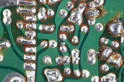
It was some years ago, while working in Danfoss Solar Inverters, when I had first-hand experience of how dramatically corrosion can affect AC drives.
I visited a grid-connected photovoltaic plant consisting of multiple two-axis solar trackers, each one with an individual IP 21 inverter installed inside its mast, so it was considered to be in ‘semi-indoors’ conditions. These inverters, after only a few months of operation, already required replacement due to corrosion of the electronics.
Why did this happen?
The plant was in a southern Mediterranean coastal area where it’s very hot and humid and exposed to a wind-driven salt and sand environment. As a result, the three main elements in the corrosion equation were present: humidity, temperature and pollutants.
How are these elements correlated? We will see in this post that humidity, temperature variations and even pollutants can cause condensation, and that existing pollutants determine how corrosive the condensate is.
First, let’s have a look at how the condensation process takes place.
Humidity is the amount of water vapor in the atmosphere. It can be given as an absolute value (g/m3), but normally it is expressed as relative humidity (RH), given in percentage terms, which is the amount of moisture in the air compared to what the air can hold at that temperature and pressure conditions. As warmer air has a higher water vapor capacity, the same RH value has a different amount of associated water vapor depending on the air temperature. For any air temperature, if the RH reaches 100%, the air cannot hold any more water and some water condenses. However, condensation may also occur at an RH below 100% if pollutants are present. For example, salt mist in coastal areas can cause condensation to occur at an RH of 75%. Other individual pollutants (like sulfur and nitrogen oxides generated in fossil-fuel combustion, ammonia present in farms, ozone and halogens) or a combination of them can result in condensation at even lower values of RH. So, to ensure that condensation will not occur, a value below 60% RH must be always maintained inside your AC drive.
When condensation and pollutants combine, the result can often be much more corrosive than the clean water and the pollutants separately (for example, when sulfur dioxide, SO2, combines with water to form sulfurous acid) and can exist in a liquid phase much longer than water alone. This corrosion can be chemical and also electrolytic or galvanic, because many pollutants dissolved in water form a conductive solution. It also affects mechanical components, but it’s more critical for electronic ones and these should be carefully protected.
The continuous operation of AC drives installed outdoors results in internal temperatures in your AC drive to be always higher than the ambient temperature. So, the risk of internal condensation and the corrosive effect of the pollutants are highly minimized inside your AC drive. However, this situation of higher internal temperature is a double-edged sword: while it’s true that it reduces internal condensation, the rate of destructive chemical reactions doubles for every 10°C/18°F increase in temperature. Because of this, an optimal cooling system for your AC drive is always required to avoid corrosion effects in polluted environments.
In other applications, with intermittent operation or no operation at all during the night (solar-powered pumping applications, for example), an AC drive can experience wide swings in both ambient and operating temperatures due to the temperature difference between day and night. The wide temperature variations promote cyclical condensation (during the night) and evaporation (during the day) increasing the likelihood of corrosion. In short, the higher the difference between day and night temperatures, the higher the probability of corrosion.
So what steps can you take to fight against corrosion? Let’s take a look at three strategies that can be followed.

Avoiding pollutants ingress
The best solution would be installing your AC drive away from the polluting environment, but this is not always possible. In this case, a combination of enclosures with higher IP/UL Type classifications and indirect cooling of electronics and other sensitive components can be used instead.
Liquid-cooled drives (for example, VACON® NXP Liquid Cooled), IP 66/UL Type 4X enclosures with indirect cooling through a heat sink (as in the VACON® 100 X or VLT® HVAC Drive) or back-channel cooling solutions (such as in the VLT® AQUA Drive or VACON® 100 FLOW) can be used for this purpose.
With all these solutions, you highly minimize the risk of corrosion over the core parts of your AC drive because they are not exposed to a constant flow of polluted cooling air.
Careful operation and a good service strategy are still required to minimize environmental impact: the activities that require your AC-drive enclosure to be opened should be reduced. The inner part of the drive would be exposed to the pollutants/humidity of the environment, which would remain inside after closing the enclosure, greatly increasing the likelihood of corrosion.
Handling condensation
We can avoid condensation by means of increasing the internal temperature of the drive when required, for example, during low ambient temperature conditions or while your AC drive isn’t in operation. This does not, in reality, dry the inner air, but instead reduces the RH and, as a result, reduces the probability for condensation to occur. This can be implemented in the real world using an internal heater controlled by a thermostat (as in the Arctic mode of the VACON® 100 X). This solution increases the operation costs by way of increasing power consumption.
Condensation can also be minimized by means of pressure equalization, as we saw in the part 3 of this blog series, using GORE® vents like those that can be found in the VACON® 20 X. This is a passive method, without the drawbacks of the internal heater solution, and additionally provides a barrier against pollutants.
If condensation cannot completely be avoided, a controlled water path out of the product can be given by design. Solutions like condensing covers or drain holes (as in UL Type 3R enclosures of the VLT® AutomationDrive) follow this principle.
How the electronic boards are mounted is also important in order to prevent condensation from accumulating on them and facilitating its drip down to the cabinet. VLT® drives, for example, are normally designed for vertical mounting of the cabinet.
Protecting the sensitive elements
Conformal coating is a common solution for protecting the electronic boards. You can find class 3C2 or 3C3 coatings in the Danfoss Drives portfolio, according to the IEC 60721-3-3 standard. This coating includes resistance to chemicals (such as chlorine, hydrogen sulfide and ammonia), fungus, moisture and flame.
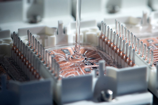
Last, but not least, encapsulation of components can be used to keep moisture and condensation away, apart from providing a very stable thermal environment and making it easy to mount them on a heat sink or similar. This approach is used in the Danfoss-Silicon-Power-manufactured power modules used in the VLT® portfolio. Power modules can be used for the rectifier and the inverter bridge of your AC drive. They consist of semiconductors (IGBTs and diodes) placed on a highly heat-conductive material, covered with a see-through silicon paste. Another example of encapsulation is potted coils (sealed in solid wax inside an aluminum box).
In conclusion, although corrosion is something to be taken into account, in Danfoss Drives we have the appropriate technical solutions to avoid ‘unpleasant surprises’ as in the case of the PV plant exposed at the beginning of this post.
Authors:
Abraham González Ponce, Application Knowledge Manager, Application & Service Products, Danfoss Drives
Jake Roeder, Global Product Marketing Manager, Danfoss Drives
