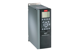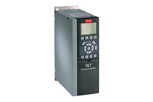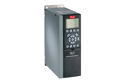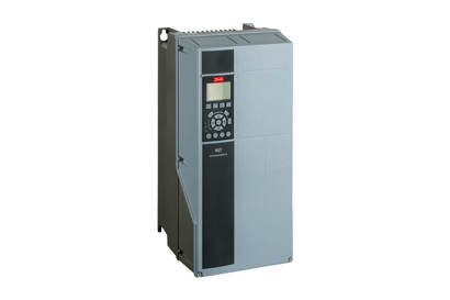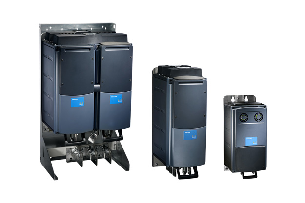
Drives are more than simple power processors
With the ability to act as sensors and sensor hubs, to process, store and analyze data, along with connectivity capabilities, drives are vital elements in modern automation systems and building management systems (BMS). Integrated condition-based monitoring functionality enables new ways of performing maintenance, such as condition-based maintenance.
Evolution of Industrial Automation Systems
In the transition to the current millennium, we have witnessed a profound change in technology, which has led to a whole new way of working in a digital world. This is the fourth industrial revolution. The first industrial revolution, which occurred during the 18th and 19th century, was a mechanical revolution, triggered by the invention of the steam engine. By the end of the 19th and early 20th century, the second industrial revolution unfolded with the adoption of mass production, electrification, and changes in communication. This period is also referred to as the Electrical Revolution. Later in the 20th century, the third industrial revolution brought advances in semiconductors, computing, automation and the internet. This phase is also known as the Digital Revolution.
The fourth industrial revolution has emerged as a result of networking computers, people, and devices fueled by data and machine learning. Although the term “Industry 4.0” is quite vague, a possible definition for Industry 4.0 describes the intelligent networking of people, devices, and systems by utilizing all possibilities of digitalization across the entire value chain.
Trends in Industry 4.0 Automation Systems
The impact of Industry 4.0 on motor systems and building management systems is a migration from the “automation pyramid” to “networked systems”. This means that the various elements of the system, such as motors, drives, sensors and controls, are interconnected and connected to a cloud - a data center where data is stored, processed, analyzed, and decisions are made.
In an automation network, the amount of data is prominent. As data is mainly produced by sensors, the number of sensors in modern automation systems is increasing. Motors and driven machines such as fans, pumps and conveyors are not the most obvious participants in a data network. Sensors are therefore required to collect data from these machines. The sensors are connected to the data network using various means to utilize the data. During the introduction of an advanced condition monitoring system, the additional cost of sensors and connectivity is often seen as a barrier.
Modern variable speed drives open new opportunities in the Industry 4.0 automation network and in building management systems. Traditionally, drives have been considered power processors for controlling the motor, fan, conveyor and/or pump speed. Today, drives are also part of the information chain, using the advantage of built-in processing power, storage capacity, and communication interface, within the drive.
Integrated intelligence
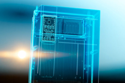
What is an intelligent drive?
In the Industry 4.0 network, the drive plays an important role and is characterized by some enabling features:
- Secure connectivity: The drive can connect to other elements in a secure manner. Other elements in the network may include drives, PLCs, sensors, and a cloud.
- The drive acts as a sensor: The drive uses motor current and voltage signature analysis to sense the motor and application performance.
- The drive acts as a sensor hub: The drive acquires data from external sensors related to the process which is controlled by the drive.
- The drive acts as a controller: The drive can replace the PLC wherever application constraints allow.
- Bring your own device concept: Wireless connectivity to smart devices (smartphone, tablet).
Information from the drive can be identified as follows:
- Instantaneous signals: Signals which are directly measured by the drive using built-in sensors. Data such as motor current, voltage, drive temperature, and their derivative, which is power as a multiplication of current and voltage, or motor torque. Moreover, the drive can be used as a hub for connecting external sensors which provide instantaneous signals.
- Processed signals: Signals which are derived from the instantaneous signals. For example, statistical distribution (maximum, minimum, mean and standard deviation values), frequency domain analysis or mission profile indicators.
- Analytics signals: Signals which provide indications of the condition of the drive, motor and application. The signals are used to trigger maintenance or lead to system design improvements.
Motor current signature analysis techniques enable the drive to monitor the condition of the motor and application. The technique allows to potentially eliminate physical sensors or extract early fault signatures which might not have been possible to detect. For example, using the technique makes it possible to detect cavitation and winding faults in advance or mechanical load eccentricity.
The concept of the drive as a sensor hub entails connecting external sensors to the drive, thus saving the need for a gateway to connect the physical sensor to the data network. Vibration sensors, pressure sensors, and temperature sensors are examples of sensors which can be connected to the drive. The advantage of the concept is not only related to cost, but also enabling the correlation of sensor data with different types of data present in the drive. An obvious example is the correlation of vibration level from an external sensor with the motor speed, as vibration is speed dependent.
Condition-based maintenance and other maintenance strategies
The following are different kinds of maintenance strategies:
- Corrective maintenance: The product is exchanged after a fault.
- Preventive maintenance: The product is exchanged before a fault, although no notifications are received from the product.
- Condition-based maintenance: The product provides a warning when the actual lifetime of the product varies from the expected lifetime and possible root causes are indicated.
- Predictive maintenance: The product provides a warning before the product reaches the designed hours of operation, in order to initiate service action.
Why is condition-based maintenance needed?
Corrective and preventive maintenance are fault (event) or time-based. Therefore, maintenance is performed in case of fault(s) (corrective) or after pre-established operation hours (preventive). These types of maintenance do not use any feedback from the actual application.
With the introduction of Industry 4.0 and the availability of sensor data, condition-based and predictive maintenance is now possible. Such maintenance strategies use actual sensor data to determine the condition of the equipment in service (condition-based maintenance) or to predict future failures (predictive maintenance).
Overview and benefits of condition-based maintenance
Condition-based maintenance is the easiest and most intuitive maintenance technique based on data from the actual application. The data acquired is used to monitor the health of the equipment in service. For this purpose, key parameters are selected as indicators to identify developing faults. The condition of a piece of equipment typically degrades overtime. This is illustrated by the P-f curve which shows a typical degradation pattern. Functional failure occurs when the equipment fails to perform the intended function. The idea of condition-based maintenance is to detect the potential failure before an actual failure occurs.
Advantages of planning maintenance actions
- Downtime reduction
- Elimination of unexpected production stops
- Maintenance optimization
- Reduction in spare part stock inventory
CBM in 3 steps
Condition monitoring functions for variable speed drives
An integral part of condition-based maintenance involves monitoring the condition of the equipment. In variable speed applications, the condition of the application often depends on speed. For example, vibration levels tend to get higher at higher speeds, although this relationship is not linear. Indeed, resonances can occur at certain speeds and then disappear when the speed is increased.
Using an independent system to monitor the condition of a variable speed application is complicated by the need for knowing the speed and the correlating monitored value with speed. Using drives for condition monitoring (“drive as a sensor” or “drive as a sensor hub”) is an advantageous solution, as the information about application speed is already present in the drive. Additionally, information about the load/motor torque and acceleration is readily available in the drive.
Condition monitoring follows a three-step procedure:
Learn more in the CBM white paper and video
Today, drives are more than simple power processors. With the ability to act as sensors and sensor hubs, to process, store and analyze data, along with connectivity capabilities, drives are vital elements in modern automation systems.
Drives are often already present in automation installations and therefore present a great opportunity to upgrade to Industry 4.0.
This enables new ways of performing maintenance, such as condition-based maintenance. The functions are already available in some drives and early adopters have already started using the drive as a sensor.

Water and wastewater monitoring
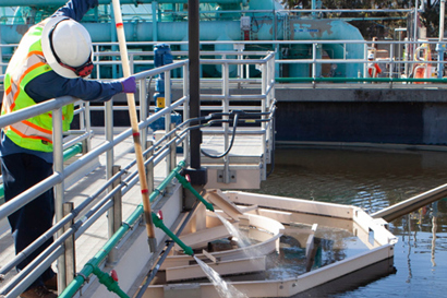
In water and wastewater applications, activating a condition monitoring system integrated into your VSDs optimizes the overall performance. Edge computing means there is no need to connect to the cloud.
Contact our expert

Is your maintenance strategy evolving to keep up with the demand for efficiency? Reach out now, and I’ll show you how CBM can transform your approach!
Highlighted products
Danfoss products using condition-based monitoring
-
if (isSmallPicture) {


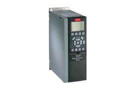
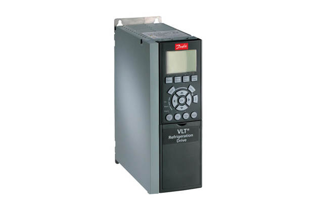
 VLT® Refrigeration Drive FC 103
FC103 is dedicated to controlling compressors, pumps and fans for significant energy savings in refrigeration plants.
-
if (isSmallPicture) {


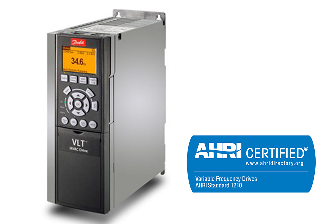
 VLT® HVAC Drive FC 102
This tough and savvy FC102 drive enhances pump and fan applications in building management systems, and runs outdoors in most climates.
-
if (isSmallPicture) {


 VLT® AutomationDrive FC 301 / FC 302
The VLT® AutomationDrive FC301 / FC302 is designed for variable speed control of all asynchronous motors and permanent magnet motors. It comes in a standard version (FC301) and an advanced high dynamic version (FC302) with additional functionalities.
-
if (isSmallPicture) {


 VLT® AutomationDrive EZ FC 321
For basic drive applications this easy to stock AC Drive with a low number of variants can get to you quickly, and is simple to startup with plug and play convenience.
-
if (isSmallPicture) {


 VLT® AQUA Drive FC 202
Maximum energy efficiency for both water /wastewater and Industrial pump/fan applications
-
if (isSmallPicture) {


 VACON® 100 FLOW
Dedicated functionality that improves flow control and saves energy in industrial pump and fan applications.
-
if (isSmallPicture) {


 VACON® 100 INDUSTRIAL
Drive modules and enclosed drives that are easily integrated into all major control systems.
-
if (isSmallPicture) {


 VACON® NXP Air Cooled
Designed for a broad range of demanding applications, focusing on higher power sizes and system drives.
-
if (isSmallPicture) {


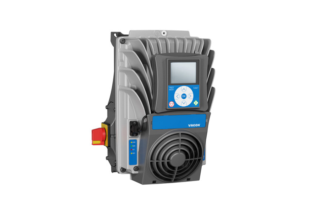
 VACON® 100 X
A drive for indoor and outdoor applications that withstands high pressure and vibration levels, water, heat and dirt.
-
if (isSmallPicture) {


 VACON® NXP Liquid Cooled Common DC Bus
Brings the benefits of liquid-cooling into common DC bus systems in demanding situations. Active Front-end (NXA), Non-regenerative Front-end (NXN), Brake Chopper (NXB) and Inverter (NXI) configurations are available.

Danfoss first innovations
CBM has emerged from a history of Danfoss firsts in innovation. Danfoss drives differentiate from others in the market with intelligent functions embedded in the drive, to reduce the external components required.

