Pack Controllers
AK-PC 551
Programming
In this video our product expert Kenn will walk you through how to program the pack controller AK-PC 551
Communication
Check that termination is done on both the controller and the MMIMYK.
The Baud rate on both the MMIMYK and the controller must be 50K.
How to check and set baud rate in the MMIMYK:
- Disconnect the MMIMYK from all power supply sources (Power might be supplied via USB cable, via connection to the controller or via external power supply)
- Reconnect power supply to the MMIMYK
- Select menu point "CAN settings" in the MMIMYK menu
- Select menu point "Baud rate" in the MMIMYK
- Check that the baud rate is set at 50K (if not, set it to 50K)
How to check and set the Baud rate in the controller:
- Disconnect the power to the controller
- Push and hold both Enter (┘) and Escape (X) buttons while you connect power to the controller
- Now you have entered the BIOS menu
- Go to CAN and push Enter
- Go to BAUDRATE and push Enter
- Go to 50K and push Enter
- Go to Node ID and push Enter
- Check that you have a legal address (otherwise set the correct address)
- Push Escape (if nothing is changed)
- Push Escape once more
- Go to Exit and push Enter
- The controller will now Boot
Now there should be communication between the MMIMyK and the controller.
If the user has a blind version (Kit) without a display on the front of the controller (option for AK-PC 551 only) the controller can be accessed via a remote MMIGRS2 display:
- Activate display by pushing one of the buttons
- Press and hold the enter (J) button until asked for password – if any!
- Enter the password (default is 300) to enter Main menu
- Go to System -> Enter
- Go to Network -> Enter
- MODBUS Baudrate (can be set to e.g. 384)
- Check that you have a legal Modbus address (change if necessary)
CANBUS Baudrate cannot be set via remote MMIGRS2 display, so it is not possible on a blind controller (Kit).
However, it is possible to set the CANBUS address of the controller via the MMIMYK.
This is how to set the CANBUS Baudrate via MYK. It is quite easy:
Program -> Config node -> Baudrate... select... ENTER
Then it takes few seconds.
Note: The communication cable between the controller and the MMIMyK has the code number 080G0075
Condenser
Condenser control
Condenser control using P- or PI-control
If the condenser control type is set to “P-control” (Proportional control), this control will allow some deviation from the reference, because it is just a P-controller with a P-band allowing a difference between the reference and the controlled value where the size of the difference is depending on the output. P-control is fast but not precise, whereas PI-control (Proportional Integration control) is precise. With PI-control the integration function will, so to speak, integrate the fault away.
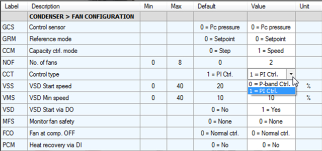
The Control Type can be set in the controller. Below it is shown how the control type is changed from P-band control to PI-control using the AK-PT 50 PC software:
Capacity control
Bitzer CRII control
When the requested capacity reaches the setting of the “Start capacity”, the compressor will start. Start capacity setting for Scroll and CRII is by default set to:
Min: 10%
Max: 60%
Fac: 30%
When the unloader valve goes ON/loads (power to the coil is OFF), the cylinders will deliver capacity.
Example with requested capacity of 10 % on a 4-cylinder Bitzer CRII:
2 seconds is 10 % of a 20 second period time and that is for each of the valves controlling 2 cylinders.
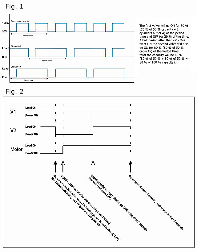
The first valve will go ON for 10 % (10 % of 50 % capacity – 2 cylinders out of 4) of the period time and OFF for 90 % of the time. A half period after the first valve went ON, the second valve will also go ON for 10 % (10 % of 50 % capacity) of the Period time. In total the capacity will be 10 % (10 % of 50 % + 10 % of 50 % = 10 % of 100 % capacity).
For fig. 1
- The minimum period time you can set is 10 seconds (nominal is 20 seconds and maximum is 60 seconds)
- The minimum time an unloader valve should be operated in loaded or unloaded state is 2 seconds
With this configuration it is only possible to go down to 20 % capacity. If it is required to go down to 10 % the period time will have to be increased to 20 seconds.
However, the initial start of compressor capacity is a bit more complicated. It is easier to make a sketch (See fig 2)
The unloaders are inversed:
Please be aware that since software version 1.20 of the AK-PC 551 controller (with Packman 2 capacity control) is taking care of the inversion of the unloading valve outputs, the digital outputs should not be inversed for the unloading valves – the controller is taking care of the inversion.
Secondly, please also be aware that whenever a compressor is at standstill, the unloading valve will be without power/loaded. Just before the compressor starts, the unloading valve is powered and the compressor is started (1-2 seconds between these two actions)
AK-PC 651A
Introduction to AK-PC 651A
In this video our product expert Edivaldo will explain the main differences between the pack controller AK-PC 651 and the successor AK-PC651A
AK-PC 782A/AK-PC 782B
In this video our product expert Edivaldo will show how to replace the AK-PC 782A with AK-PC 782B

In this video, our product experts Edivaldo and Premnath will show how to connect AK-PC 782B to AK-SM 800A

In this video, our product expert Edivaldo will look at how to use the AK-PC 782A/B for controlling Heat Recovery.

The AK-PC 782B was designed to use Ethernet connection to the System Manager, through the router – check the video “How to connect AK-PC 782B to AK-SM 800A” in this webpage for connection details.
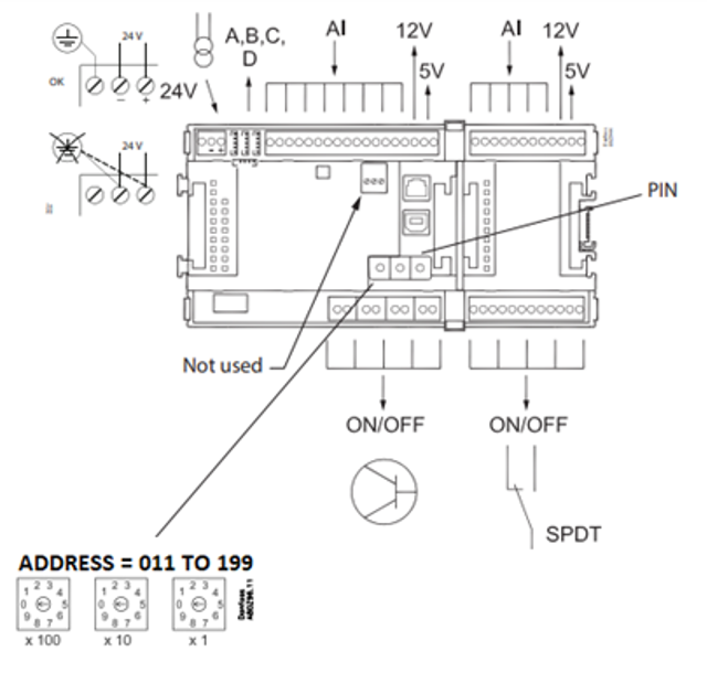
To configure the network address of the AK-PC 782B, the valid range of addresses is between 011 to 199, as shown below in the Installations Guide and User Guide:
The AK-PC 782B was designed to operate in this range of addresses. However, if by mistake the address is set to 001 to 010, the AK-PC 782B might not be able to communicate properly with the System Manager.
Miscellaneous
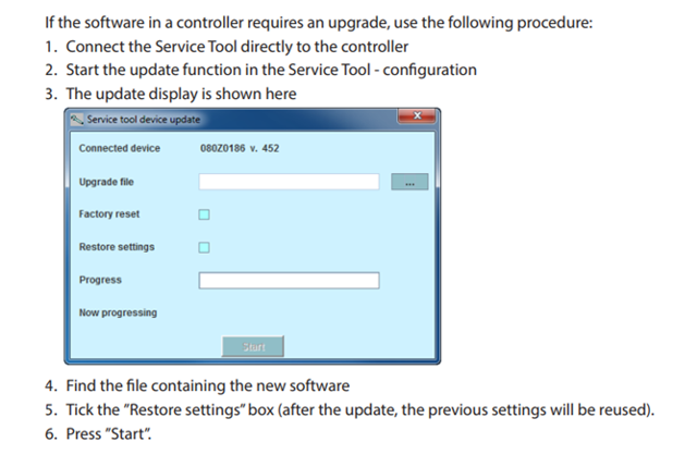
The image below comes from the AK-ST 500 manual:
Compressor capacity control
Pump-down of lead compressor
If a lead compressor is defined, the pump-down function can be enabled. In this explanation a VSD compressor is selected as lead compressor. This compressor will be the first compressor to start and the last to stop. The lead compressor will stop when the “Requested capacity” reaches “0 %”. The “Control temperature” will be lower than the “Reference” (“Setpoint”).
It is possible to set up a “Pump-down” function which will allow the lead compressor to keep on running until it has reached the “Pump-down limit Po” which should be set to a value somewhat lower than the “Setpoint”. Still the “Requested capacity” has to reach “0 %” before the VSD compressor stops.
Pros and cons using pump-down:
The lead compressor will keep running for a longer period which could lead to fewer stops/ starts. By keeping the lead compressor running at lower suction pressure, the COP of the application will suffer. This will increase the power consumption.
Capacity control can be done using an S4 media temperature sensor instead of the pressure transmitter. If S4 is used, the pressure transmitter is only used as safety e.g. as frost protection.

