Case Controllers
Defrost
Hot Gas Defrost sequence-AK-CC55
In this video we will show an animation of the hot gas defrosting procedure using a Danfoss AK-CC55 single coil controller.
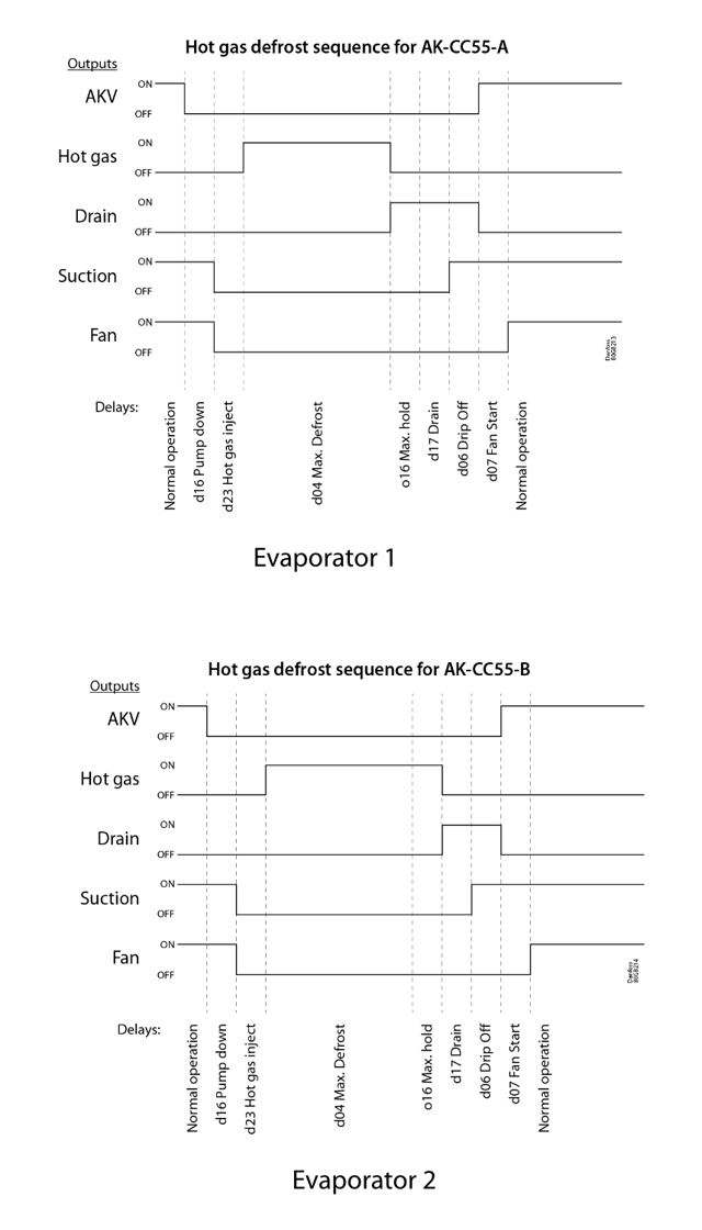
Here the Hot Gas Defrost sequence for case controller AK-CC55 is described.
The principle and sequence of hot gas defrost is also used in many other types of case controllers like AK-CC 200/300/450/550/750. Some controllers have solenoid valves instead of AKV valves and some do not have drip tray heaters. Apart from that the sequence is the same.
The outputs on the AK-CC55 used in the hot gas defrost sequence are (Application 5):
- AKV valve
- Hot gas valve
- Drain valve
- Suction valve
- Fan
Evaporator 1: This will finish defrost first in a coordinated defrost sequence
Evaporator 2: This will finish defrost last in a coordinated defrost sequence: (In this example max. hold time expires immediately after defrost stops. The max. hold time should be set to the same time as max. defrost time)
d16 – Pump dwn del. (Pump down delay):
Set the time for when the evaporator is emptied of refrigerant prior to defrost.
d23 – HotGasInjDel (Time delay before opening of hot gas valve):
This allows time for a PMLX valve in the suction line to close (if used).
d04 – Max Def. time (Max. defrost duration):
This setting is a safety time stopping the defrost if there has not already been a stop based on temperature or via coordinated defrost.
o16 – Max HoldTime (Max. standby time after coordinated defrost):
When a controller has completed a defrost, it will wait for a signal telling that the refrigeration may be resumed. If this signal fails to appear for one reason or another, the controller itself will start the refrigeration when this standby time has elapsed.
d17 – Drain del (Drain delay (only in connection with hot-gas)):
Set the time for when the evaporator is de-pressurized and emptied of condensed refrigerant after the defrost.
d06 – DripOff time (Drip-off time):
The time that has to elapse from the hot gas valve is closed and until the injection may start again (the time when water drips off the evaporator). This function is normally not used together with hot gas defrost – drain delay will normally take care of drip off too.
d07 – FanStartDel (Delay of fan start after defrost):
The time that has to elapse from injection start and until the fan may start again (the time where liquid water drops are freezes onto the surface of the evaporator).

Fan
ECO function in AK-CC55
The ECO function is a low-speed fan function, where two DOs are used. This can only be achieved when using Application 9 in which it is possible to define an extra “Fan 2” output to trigger low speed of the EC fan motors. “Fan” will start the fan(s) at high speed and “Fan 2” will reduce the speed. When fans are running ECO/Low speed the display will show “ECO”.
ECO can also be activated during night operation, where the ECO function is used when night curtains are closed on the case. Please be aware, however, that ECO is not possible if the heating or defrost function is active (if the controller has been set up for this).
If the controller is set up with two-step EC fans, “ECO” will show in the display at low speed where both DO outputs are active.
Configuration:
Configuration of relay output DO2 (e.g. Single Coil, application 9): 0=not used, 1=fan, 2=fan Eco, 3=defrost, 4=rail heat, 5=alarm, 6=light, 7=night blinds, 8=compressor, 9=compressor 2, 10=heating element
Please note: Adaptive defrost cannot be used with two-step fan control.
Injection
Adaptive Liquid Control function for AK-CC case controllers
“ALC” is a case controller function which stands for “Adaptive Liquid Control”. “CALM” stands for “CO2 Adaptive Liquid Management”, which is a total system level solution.
The following case controllers have the ALC function included:
AK-CC 550F – 084B8073 – to be discontinued
AK-CC 550A – 084B8030 with software version 2.01 released in January 2019
AK-CC 550B – 084B8032 with software version 2.01 released in November 2018
AK-CC 750A – 080Z0140 with software version 1.21 released in October 2018
AK-CC55 – 084B4081, 084B4082, 084B4083 and 084B4084 released in February 2020
For more detailed information, please contact Global Product Support.
How to set up the ALC and CALM functions:
CALM is a Master Control function which is set up in the system manager. The liquid level (ON/OFF signal) in the suction accumulator, the pack controller status and the pump envelope for the Liquid Ejector calculated by the AK-PC 78xA pack controller determines whether the case controllers can be allowed to run with ALC or not (normal MSS control).
ALC can also be set up directly in the case controllers. The input is the liquid level ON/OFF signal from the suction accumulator connected to the DI1, DI2 or DI3 input on the case controller (setting value = 21 (Switch to operation with ALC when the input is short-circuited)).
It should be mentioned that there is no check of the pack status or ejector envelope using direct connections.
If the ON/OFF signal is connected on the dry contacts DI1 or DI2, it is important that all controllers receiving the signal from the contact are wired correctly with Ground to Ground and Signal to Signal. Mixing will make the function fail.
An example of how it works: The connector 25 (DI1) on AK-CC 550A sends out a short current signal every second to check whether the DI contact is closed or open. If the contact is closed (low level), the voltage across the DI input is pulled down by connector 24 (Ground).
It is important that none of the case controllers connected are powered off because this will make the function fail. If it is necessary to power off controllers, an auxiliary relay is needed.
If the high voltage input is used, the wiring will also have to be done right to avoid shortcuts but it does not matter which of the DI input goes to L (line) or 0 (neutral).
Superheat control:
There are two parallel settings for superheat:
1. Dry expansion, which does not allow liquid flow
2. ALC, which allows liquid flow. This type of control requires that the controller receives an on/off signal from (for example) a tank in the suction line. A level switch in the tank will register when the liquid level is exceeded. When this happens, the controller will switch to dry expansion, and then back to ALC when the liquid level has dropped. The function is defined in setting o02, o37 or o84. The function can also be received via data communication from a system manager.
How do I exchange an AK-CC 550 with an AK-CC55?
Learn how to replace the AK-CC 550 with the AK-CC55. In this video, Kenn Sønder Jensen guides you through replacing the AK-CC 550 with the AK-CC55. Discover how easy it is to replace the controller, what you should be aware of when doing so, and how to avoid pitfalls.

Showing you how to replace an AK-CC 550A with an AK-CC55, product expert Premnath Kangatharan guides you through the steps you need to know to effectively change your case controller in the interface of the AK-System Manager 8xxA series. Get familiar with the new System Manager interface and ensure you get your new case controller up and running quickly.

Technical data
DO relays for capacitive loads – AK-CC55
DO relays for Fan and Light are designed to cope with capacitive loads like EC fans and LED light.
DO2 (Light) and DO3 (Fan) for AK-CC55 Compact and DO5 (Light) and DO6 (Fan) for AK-CC55 Single Coil and Multi Coil are dimensioned according to the TV-5 standard where the maximum capacitive or inductive load can be up to 80 A. These outputs can be recommended for EC fans and LED light.
All relays are sealed for use with flammable refrigerants like R290 propane.
Compliance with EN 60 335-2-89: 2010 Annex BB.
| For relays DO2, DO3, DO4, DO5 and DO6 the following data apply*: | 115 V / 230 V AC |
| Load max.: | CE. 8 (6)A UL. 8A res. 3FLA 18LRA |
| Load min.: | 1VA |
| Inrush: | DO2, DO3 for Compact DO5, DO6 for Single/Multi Coil TV-5 80A |
*DO2, DO3, DO4, DO5 and DO6 are 16 A relays but Maximum load must be observed. DO3 and DO4 for Compact and DO5 and DO6 for Single/Multi Coil is recommended for EC Fan and LED light.
Please note that the 8 A maximum load is a continuous load while the inrush load is just short bursts.
The relay specifications can be a bit confusing, but there are no faults in the data.
The relays are set to a maximum current of 8 A resistive/ohmic load and 6 A with inductive load (for coils).
This is the maximum current load and must not be exceeded!
However, the physical relay is marked 16 A if the controller should be opened to check the circuit. The reason for a lowered specification is that there is a need for a long-expected service life and a certain number of ON/OFF cycles. This in order to provide a high quality product.
User interface
Communication Status U45 checks signal quality for MODBUS-AK-CC55
Comm. Status U45 with measuring range: 0 – 100 %
The parameter U45 displays a check of signal quality for the MODBUS communication.
The quality of communication is continuously validated, and a communication status (0 – 100 %) will be read out in the display menu or in a remote monitoring device. Furthermore, the communication status can also be found in the AK-ST 500 Service menu. (The communication quality status is read out in the “U45 Comm. Status”.)
The communication quality status will only include received bus telegrams and only on MODBUS communication (not on LON communication).
If no telegrams are received, a useful communication quality status cannot be given (nothing is read out).
It is estimated that the value should be at least 80% on a good network – a value lower than that should be investigated.
The Comm. Status U45 can be seen on both the Info display and the Setting display. Furthermore, it can be found in the Bluetooth display here:
Parameter menu -> Miscellaneous -> Network -> (Shift from Settings to Readout) Communication status
Introduction to the AK-CC55 Connect App
In this video, our product expert Paul will look at how to set up the AK-CC55 Connect App.

Wiring
Display cable length for AK-CC55
There are three display variants available for an AK-CC55 controller:
- AK-UI55 Set (keyboard version)
- AK-UI55 Info (display only)
- AK-UI55 Bluetooth (Bluetooth version)
Up to two displays can be connected to an AK-CC55 case controller via RJ12 connectors.
If only one display is connected to the controller, the maximum cable length is up to 100 meters.
If two displays are connected, their combined cable length can be up to maximum 100 meters from the controller.
Example with two displays:
If e.g. one display has a cable length of 20 meters and the second display has a cable length of 80 meters, the combined length is 20 + 80 = 100 meters, which is acceptable.
AK-CC55 Water Loop Controller
In this video our product expert Kenn will give an introduction to the AK-CC55 Water Loop Controller.


