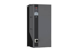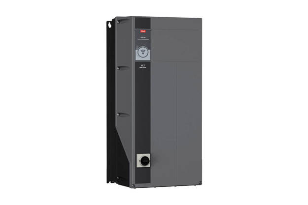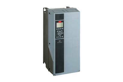
Integrated vibration analysis
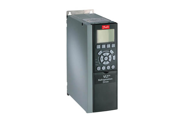
Danfoss drives offer unique integrated condition-based monitoring (CBM) functionality. For installed machines currently with no access to condition monitoring data, these drives provide a convenient way to implement monitoring and begin collecting performance data.
Along with stator winding monitoring and load envelope, the CBM functionality integrated into the drive includes vibration monitoring. Vibration monitoring is realized with the help of vibration sensors, required for signal collection. The drive supports up to four vibration channels, connected to the analog inputs, 4-20 mA.
Vibration monitoring comprises 2 functions:
- General overall vibration level monitors mechanical vibration and is useful for early detection of main malfunctions such as imbalance, misalignment, mechanical looseness.
- The second function uses a different type of sensor calculated value, useful for monitoring bearing degradation, poor lubrication, and more.
The two functions are complementary to each other. The sensors provide a calculated output of a general vibration (v-rms) or bearing condition in wider frequency range (g-rms).
Condition monitoring vibration analysis
In the Danfoss implementation, the vibration is always correlated with motor speed. This is valuable because Danfoss drives offer thresholds adaptable to the state of operation, as opposed to general monitoring using absolute values for the entire speed range. This capability is unique in variable speed operated machines.
The Danfoss vibration monitoring functionality is not a diagnostic system, being able to monitor the change between baseline data and actual values via thresholds. However, the best results in vibration monitoring are always connected with the observation of the change, and a key factor is permanent monitoring of the speed function.
According to the mechanical vibration standard ISO 20816-8:2018, the drive output of the monitoring function must comprise two warnings and one alarm, all selectable. The user receives a notification to acknowledge the status change of the monitored asset and plan maintenance accordingly. This early warning is vital for operators in being able to act fast to prevent unplanned downtime of the application.
In addition to vibration monitoring, the sensors can be useful in determining resonance points from the baseline data, as well as overall machine health, increasing the customer value.
Vibration sensors from Hansford Sensors portfolio
Danfoss has entered a partnership with the global vibration leader, Hansford Sensors (HS). CBM vibration monitoring has been developed, tested, and validated using HS sensors. Hansford is a specialist in vibration theory, sensor selection and placement, and the partnership is mutually beneficial for both companies. Hansford manufactures high quality products with lifetime warranty.
Sensor installation, placement, and mounting type
Danfoss offers two types of sensors based on body shape:
- Flat based: This body type is optimized for installation on prepared flat surface spots on the motor or machine, or to be used with mounting accessories. Mounting accessories are helpful when drilling/threading into the motor or machine is not an option. (Glue stud or magnet). Both accessories have a matching M8 female.
- Conical: Easy to install on round surfaces, where we cannot obtain flat spot on the bearing housing. Very useful for smaller motors < 11kW. HS-D20C
Positioning of sensors
There is a difference between optimal placement for v-rms and g-rms sensors.
Placement of the v-rms
HS-D20 used for monitoring imbalance, misalignment, and looseness is always on a rigid element of the motor housing. Ideally, position it on the drive end bearing or as close to this as possible. Some motors come prepared with a flat surface. The sensor can be mounted by drilling/threading or with a glue stud or even using a magnet if the surface is magnetic. There is less risk of signal loss for this type of RMS measurement.
Regarding axis, sensors can be mounted vertically or horizontally, as close as possible to the drive end bearing.
One sensor per motor is sufficient for motors rated up to 15 kW. For larger frame designations, we recommend multiple sensors, in a combination of types (v-rms and g-rms).
If only one sensor is installed, it is always good practice to measure both axes and select the one with higher level of vibration for permanent installation. The higher vibration is caused by structural resonance, stiffness, or freedom of movement, and it is important to determine the predominant direction.
The g-rms or bearing sensor
HS-D22 measures higher frequencies up to 5 kHz which do not transfer in the motor housing obviously. It measures the condition and lubrication of the bearing on which housing it is mounted. Therefore, mounting on the bearing housing is a must. Quality of the mounting is important for signal consistency. Achieve the best connection by drilling.
Electrical connection
For Danfoss drives, connect the sensors to terminal T12 (white) or terminal T13 for 24 V supply and AI53 (black) or AI54 for signal.
How to purchase sensors for use with integrated CBM functionality in Danfoss drives
| Danfoss ordering number | Hansford Sensors number | Description |
| 134B8492 | HS-D22B10 | Transducer 0-10g, 4-20mA |
| 134B8493 | HS-D20C0255019 | Transducer 0-25mm/s, 4-20mA, RMS, with M8 mounting, conical base |
| 134B8494 | HS-D20CRT0255408 | Transducer 0-25mm/s, 4-20mA, RMS, with temperature PT100 |
| 134B8496 | HS-AC334-10 | Cable 10m for 8492 and 8943 |
| 134B8497 | HS-AC010-10 | Cable 10m for 8494 |
Explore more opportunities with condition-based monitoring(CBM)
Highlighted products
Danfoss products using condition-based monitoring
-
if (isSmallPicture) {


 VLT® Refrigeration Drive FC 103
FC 103 is dedicated to controlling compressors, pumps and fans for significant energy savings in refrigeration plants.
-
if (isSmallPicture) {


 VLT® HVAC Drive FC 102
This tough and savvy FC102 drive enhances pump and fan applications in building management systems, and runs outdoors in most climates.
-
if (isSmallPicture) {


 VLT® AQUA Drive FC 202
VLT® AQUA Drive FC 202 controls all types of pumps and comes equipped with a cascade controller.
-
if (isSmallPicture) {


 VACON® NXP Grid Converter
Air- and liquid-cooled drives specifically designed for smart grid, energy storage, green hydrogen, power conversion and marine energy management applications.
-
if (isSmallPicture) {


 VACON® NXP DCGuard
VACON® NXP DCGuard™ delivers reliable short-circuit protection of DC grids for full selectivity between DC grids, and ensures fast disconnection in the event of a fault.
-
if (isSmallPicture) {


 VACON® NXP Liquid Cooled Common DC Bus
Brings the benefits of liquid-cooling into common DC bus systems in demanding situations. Active Front-end (NXA), Non-regenerative Front-end (NXN), Brake Chopper (NXB) and Inverter (NXI) configurations are available.
-
if (isSmallPicture) {


 VACON® NXP Liquid Cooled
Well-suited to applications where air quality is critical, space is limited and efficient heat transfer is required. Active Front-end (NXA), Non-regenerative Front-end (NXN), Brake Chopper (NXB) and Inverter (NXI) configurations are available.
-
if (isSmallPicture) {


 VACON® NXP DC/DC Converter
Maximizes the energy yield in hybrid solutions and helps improve performance by bringing energy support close to the consumption.

Danfoss first innovations
CBM has emerged from a history of Danfoss firsts in innovation. Danfoss drives differentiate from others in the market with intelligent functions embedded in the drive, to reduce the external components required.
Case studies
Coming soon...
Coming soon...


