Two-pipe heating and cooling systems are characterized by changing conditions due to valves opening and closing depending on the demand for heating or cooling. This continuously causes flow and differential pressure changes.
Without proper measurements, such systems suffer from uneven heat distribution, noise and energy inefficiency. Automatic balancing valves are the best option for these types of systems. Once installed, they optimize the system under all possible loads by controlling the differential pressure. In combination with pre-setting valves ensuring the correct flow through each radiator, and floor heating loop or cooling Terminal Unit, the system is optimized for the best possible temperature control, energy savings and noise reduction.
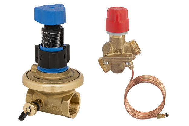
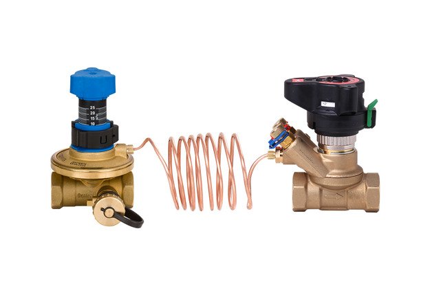
Danfoss offers a broad range of automatic balancing valves, partner valves and related accessories.
- Return pipe mounted differential pressure controllers type ASV-P and ASV-PV
- Flow pipe mounted partner valves for ASV, type ASV-BD, ASV-M and ASV-I
- Flow pipe mounted combined automatic balancing, flow limiter and zone control valves type AB-PM
Features and benefits
Less complaints
The right balance will be there under all loads, resulting in less to no complaints regarding uneven heat distribution or system noise.
Better temperature control
With the automatic balancing you will achieve better temperature control in the rooms.
Energy savings
No overflows will occur in the system anymore, resulting in no waste of energy.
Save on commissioning
There will be no measuring needed for adjustments, which will mean significant savings on commissioning costs.
Effective project planning
Projects can be handled and handed over in stages, making project planning and execution easier.

Automatic balancing valves video
This animation shows how automatic balancing valves can be a great solution to improve the performance of a heating system and reduce costs at the same time.
Product range
-
if (isSmallPicture) {


 AB-PM Automatic balancing valves
AB-PM is a combined balancing valve providing both differential pressure control and flow limitation. The valves eliminate pressure fluctuations at full load and partial load conditions and can be equipped with an actuator to allow zone control.
-
if (isSmallPicture) {


 ASV Automatic balancing valves
ASV automatic balancing valves provide a dynamic balancing solution for two-pipe heating or cooling applications. The riser-mounted valves eliminate pressure fluctuations occurring in variable flow systems at partial load conditions. For a proper hydronic balance the valves should be combined with pre-setting valves.
-
if (isSmallPicture) {


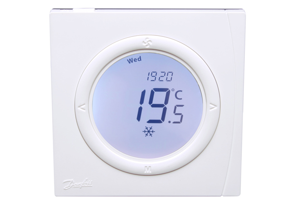
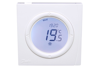
 GreenCon on/off room thermostats
GreenCon on/off room thermostats are used for room temperature control in fan coil units cooling and heating systems. By controlling room temperature in accordance with the temperature desired by user, GreenCon provides high energy efficiency while upholding and ensure optimal thermal comfort in the room.
Documents
| Type | Name | Language | Valid for | Updated | Download | File type |
|---|---|---|---|---|---|---|
| Application guide | Application guide | Italian | Italy | 07 Mar, 2021 | 10.1 MB | |
| Application guide | Application leaflet | Lithuanian | Lithuania | 18 May, 2021 | 19.0 MB | |
| Brochure | Energy saving solutions for renovation of heating and cooling systems | Polish | Multiple | 19 Feb, 2019 | 5.9 MB | |
| Brochure | Energy saving solutions for renovation of heating and cooling systems | Romanian, Moldavian, Moldovan | Romania | 01 Sept, 2014 | 6.4 MB | |
| Brochure | Energy saving solutions for renovation of heating and cooling systems | Hungarian | Hungary | 01 Sept, 2014 | 6.4 MB | |
| Brochure | Energy saving solutions for renovation of heating and cooling systems | English | Multiple | 10 Sept, 2014 | 5.9 MB | |
| Brochure | Grow your business and discover the value of working with one partner (International version) | English | Multiple | 19 Nov, 2015 | 5.6 MB | |
| Brochure | Grow your business and discover the value of working with one partner (International version) | Slovak | Slovakia | 23 Mar, 2021 | 16.4 MB | |
| Application guide | HVAC Application guide | Spanish, Castilian | Spain | 02 Feb, 2022 | 8.7 MB | |
| Application guide | HVAC Application guide | Polish | Poland | 14 Jun, 2021 | 11.3 MB | |
| Application guide | HVAC Application guide | Czech | Czech Republic | 18 Nov, 2014 | 7.3 MB | |
| Application guide | HVAC Application guide | Latvian | Latvia | 21 Apr, 2021 | 20.2 MB | |
| Application guide | HVAC Application guide | English | Multiple | 26 Oct, 2020 | 19.4 MB | |
| Application guide | HVAC Application guide 2021 | Hungarian | Hungary | 21 Sept, 2021 | 11.7 MB | |
| Brochure | Hydronic Balancing & Control product overview | English | United Kingdom | 11 Nov, 2014 | 7.1 MB | |
| Brochure | Hydronic Balancing & Control product overview | Italian | Italy | 07 Mar, 2021 | 1.0 MB | |
| Brochure | Hydronic Balancing & Control product overview | German | Multiple | 30 Aug, 2022 | 1.6 MB | |
| Brochure | Hydronic Balancing & Control product overview | German | Switzerland | 14 Oct, 2022 | 1.8 MB | |
| Brochure | Hydronic Balancing & Control product overview | Czech | Czech Republic | 18 Nov, 2014 | 1.0 MB | |
| Brochure | Hydronic Balancing & Control product overview | English | Multiple | 12 Dec, 2016 | 1.1 MB | |
| Application guide | Planner Manual Hydraulic | German | Multiple | 01 Apr, 2021 | 16.5 MB |
Drawings
Software
Danfoss SET 365 software
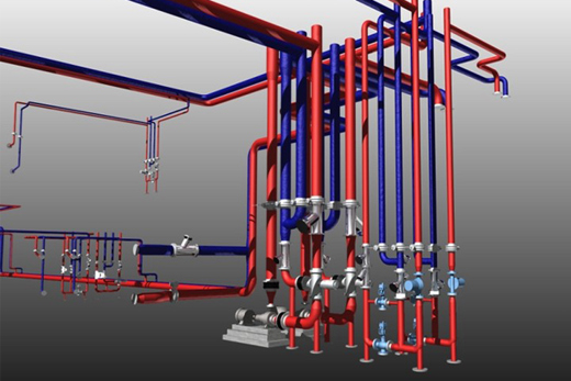
Our advanced Danfoss SET 365 3D design software will help you to design and calculate HVAC systems with Danfoss products. A 1-year subscription is FREE available for students, designers and other interested professionals.
Learning
-
 Whitepaper: Create energy efficient heating systems
PDF 4,4 MBHere you can download practical guidelines for creating energy efficient multi-family residential heating systems
Videos
Case studies
-
if (isSmallPicture) {


 New heating system with ASV automatic balancing valves in apartment building, Tallinn, Estonia
Too warm, too cold, and no chance to regulate the heating inside the individual apartment – those were the issues facing the residents in a 9-storey apartment building in Tallinn, Estonia. By upgrading the existing one-pipe system into a two-pipe system with automatic hydronic balancing, the residents now enjoy improved comfort and 25 percent savings on the energy bill.
-
if (isSmallPicture) {


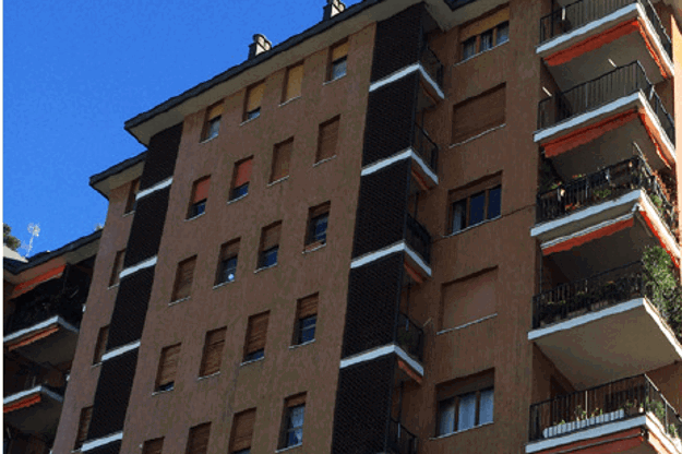
 Hydronic balancing with ASV in residential building, Milan, Italy
Some years ago, the radiators in five 9-storey apartment buildings in Milan, Italy were equipped with thermostatic radiator valves. Not until the system was fitted with automatic balancing valves, however, did the benefits of the new TRVs materialize in terms of 14 percent energy savings, less noise from the heating system and improved indoor comfort for the residents.
-
if (isSmallPicture) {


 Hydronic balancing for a housing association, Mjolby, Sweden
Energy efficiency and indoor comfort are top of mind among building owners today. Also in Sweden, where the housing association “Bostadsbolaget AB” in Mjölby took action when they were confronted with a rising energy bill due to insufficient heat distribution in a 10-storey residential building.
-
if (isSmallPicture) {


 ASV automatic balancing valves in buildings in 4 streets, Jonkoping, Sweden
During the past few years a huge demand for sustainable living has emerged. The pressure on creating environmental friendly or green buildings is higher than ever. Also for existing buildings the need for not leaving a big blueprint on the globe is becoming increasingly important. In Jönköping, Sweden, the community living in the Västerkåkar neighborhood is going forward. In 2013 substantial changes to the communal heating system in the buildings in four streets showed that a green example can be set, in just a couple of steps.
-
if (isSmallPicture) {


 Balancing valves in Sky Tower, Wroclaw, Poland
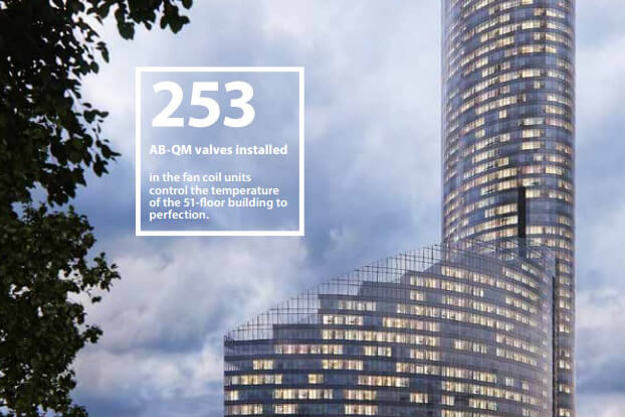
The tallest building of the EU now resides in Wroclaw in Poland. As a beautiful landmark to modern architecture, high user comfort and sustainable practice, the 212 meter high Sky Tower forms the pleasant setting for thousands of people living and working in the building.
-
if (isSmallPicture) {


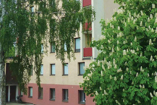
 Renovation of one-pipe system in 6 building system, Poland
A building co-operative in Szczecin, Poland, has reduced the energy consumption in their one-pipe heating system by 18 percent with a solution five times cheaper than a conversion to a two-pipe system.

